Stake attention in this memory
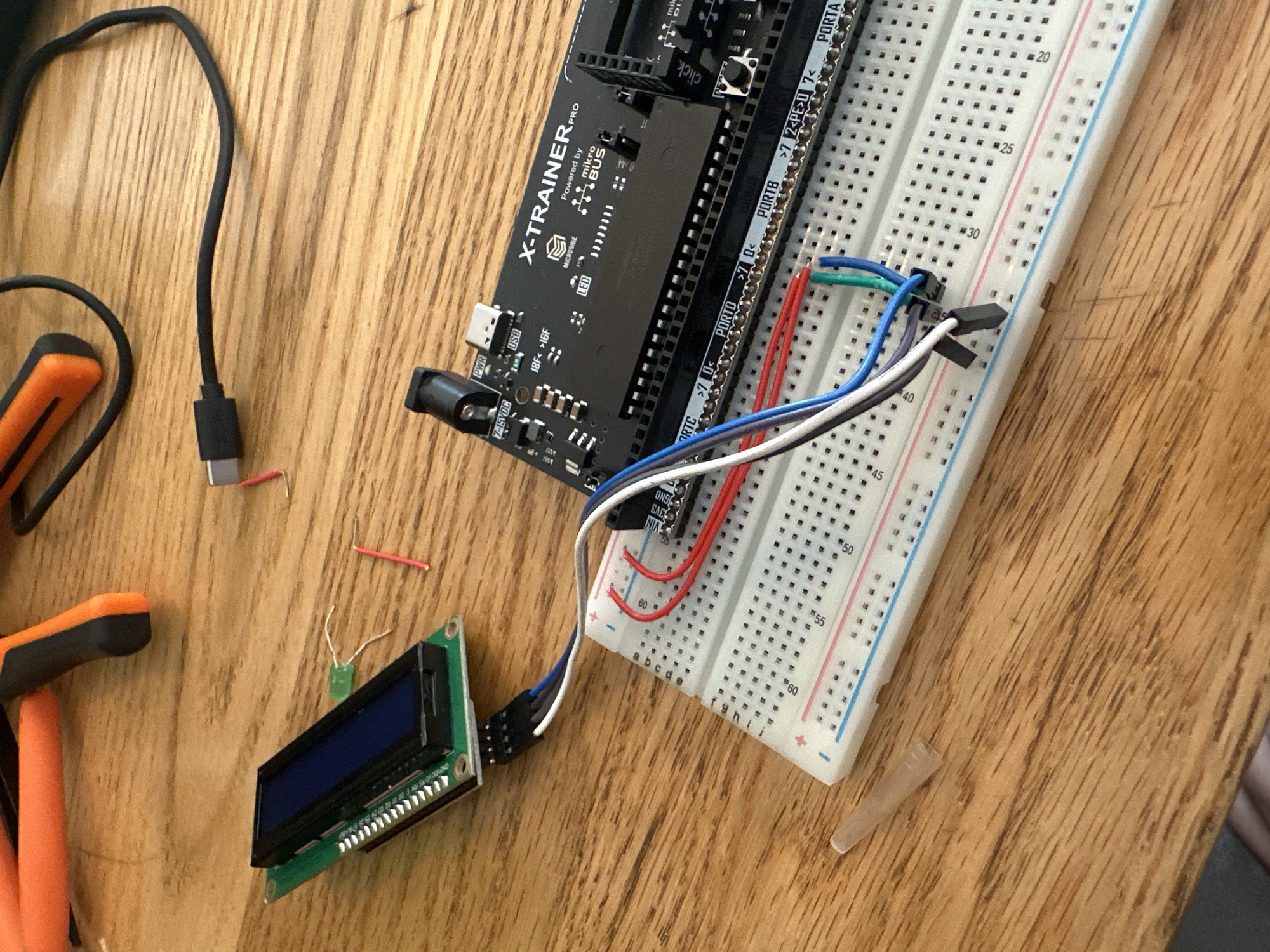
An overhead shot displays an electronics prototyping setup on a light wooden table. The primary components include a black X-TRAINER PRO development board, a white breadboard, and a small green LCD module. The X-TRAINER PRO board, prominently labeled, features various ports and headers, and text like "Powered by mikro BUS," "MICROE," "PWR," "USB," "7-15VDC," "LED," "18F," "16F," "PORTO," "PORTB," and "PORTA" is visible. A tactile "click" button is also present. It is connected via multiple colored jumper wires (red, blue, white, gray, green) to the breadboard. The breadboard has numerical markings along its side, from "20" to "60," indicating rows. Several jumper wires extend from the X-TRAINER PRO board into the breadboard, and from the breadboard to the LCD module. Some red wires are connected to the power rails (+ and -) of the breadboard. The LCD module has a header with visible pin labels such as "GND VDD V0 RS RW E D0" (and likely D1-D7). A small black connector with multiple pins connects the LCD module to a ribbon of colored wires which then go to the breadboard. Loose components scattered on the table include a black USB cable with a USB-C type connector, two small orange-handled wire strippers, two short red wire segments, a green LED, and what appears to be a small transparent plastic cap or tip. The scene suggests an active electronics project or experiment.
Symbol
D6CB9
Volume
37
Creator
+$0.00
Revenue
+$0.00
TVL
$0.01
2
Rev Bot 🤖💰
Injected revenue 1mo ago
“Revenue bonus for the last stake.”
+$0.00 USD